In the days when a couple of million miles of telephone and telegraph
circuits were carried on open-wire lines in the U.S., the Bell companies had a
strong interest in improved designs for insulators. For example, a telephone
call from New York to San Francisco in 1920 went through wires supported on, at
the usual figure of 40 poles per mile, about 134,900 pairs of insulators. The
tiny electrical leakages occurring in one pair could be magnified by sheer force
of numbers into a significant problem. So it was natural that Bell Telephone
Laboratories would concern itself with development of communications insulators.
An interesting description of the "state of the art" fifty-plus
years ago is in the following article, "Telephone Lines Insulators" by
C.D. Hocker in the March, 1930 issue of the Bell Laboratories Record. It
summarizes the results of a 32-page, painstakingly technical investigation of
insulator designs published as "A Study of Telephone Line Insulators"
by L.T. Wilson in the October, 1930 edition of the Bell System Technical
Journal. The Wilson article reports the results of tests on what we would
recognize as the "toll" (CD 121), "double petticoat (CD 154),
"CW" (CD 122.4), and "CS" (CD 128) insulators, plus some
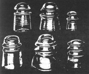
experimental types. One of these is the mushroom-shaped item in the drawing
(Fig. 1) A photograph (Fig. 2) in the May, 1936 Bell Laboratories Record shows a
test rack on a rooftop holding better than 60 of these experimental insulators,
covered with ice and undergoing evaluation.
By C. D. HOCKER
Outside Plant Development
The telephone plant requires of an insulator much more than merely that it
hold the line wire up off the crossarm. Many of these requirements are common to
all insulators. But precisely what is required of any one in particular varies
to some extent with the circuit served and the plant associated. An insulator
well adapted to one job may be far less so to another. Properties important to
its function belong not only to constituent materials, but to design and method
of mounting. Thus the development* of insulators must concern itself with the
improvement of their general and basic properties and with their refined
adaptation to special purposes.
[* The science of insulator materials and designs discussed in this
article has been developed over a period of many years. Engineers of the
American Telephone and Telegraph Company have been responsible for much of the
advance in the field of carrier-current insulators.]
Preeminently an insulator is asked to insulate.
In service it should occasion no more loss in signaling power than is warranted
in the circuit it serves. In the case of direct current, and low-frequency
alternating current signaling circuits, the sum of all the transmission losses
occurring in the insulators, pins, and crossarms is small compared with the
losses due to the resistance of the line wires themselves. An insulator used
in such a circuit has chiefly to obviate undue losses of power by leakage over
its surface, through the mounting pin and crossarm and thus to the insulator paired with it. This surface leakage is
kept small, by proper choice of both the design and material of the insulators.
The most important design feature is the provision of a suitable petticoat which
will preserve a well protected dry path. The petticoat may be a double one when
a particularly long dry path is needed. The choice of material for making the
insulators is important in maintaining low surface leakage. A transparent
material is best for telephone line insulators because the ingress of light
discourages insects from building, under the insulator petticoat, nests which
increase the conductivity of the dry path. Thus porcelain insulators, which may
be very good when new, deteriorate in service much more rapidly than glass,
because of this bothersome habit of the insects.
To meet the needs of the
telephone plant for insulators on non-carrier-current circuits, the insulators
which are chiefly used are: exchange insulators, employed on subscribers' loops
and other non-toll circuits; toll line insulators, used on the shorter toll
lines; and DP (double petticoat) insulators, used principally on the longer toll
lines. All of these are made of ordinary soda-lime glass.
The
insulators required for carrier-current circuits need to have special
electrical properties to keep down power losses in the circuits they serve. In
these circuits, now bearing currents of frequencies up to about 30,000 cycles per second, there is a substantial
power loss at the insulators due to absorption by the glass as well as to the
leakage over the surfaces. In fact, where ordinary soda-lime glass insulators
are used on high-frequency carrier-current circuits, the losses in the insulators form a large part of
the total losses, particularly in wet weather. Accordingly, carrier-current
insulators made of a special "low loss" glass are used as extensively
as possible. These insulators are styled by double initials, such as CS, CW, or
CM. The initial "C" denotes carrier-current application; "S
denotes their intended use on steel pins, "W" on wooden pins, and
"M" in mid-span installations.
Above, carrier-current insulators, of "low-loss" glass;
left to right: CS, CW, CM. Below, non-carrier-current
insulators, of soda-lime glass; left to right:
Toll line, DP, Exchange
Special "low loss" glass is
desirable for use in making carrier-current insulators chiefly because of
two properties. It is highly resistant to surface etching on prolonged exposure
to the weather, and it has the favorable electrical characteristics of a low
dielectric constant and a low dielectric absorption. Like all glasses, this
special product is a fused non-crystalline combination of acidic constituents,
primarily silica, and of alkaline ingredients, but particular choices of these
two constituents and their proportions are necessary to produce glass having the
desired properties. Specifically, the glass is of the borosilicate type, a type so called because the acidic ingredients are a combination of
boron oxide and silicon oxide (silica). In this respect it differs from the
ordinary lead, soda-lime, and soda. lead glasses, which employ silica as the
only important acidic element and are distinguished by the alkali used -- lead
oxides, or combinations among lead oxide, soda and lime. Ordinary green glass is
a soda-lime glass, owing its green color to accidental impurities of iron in
the sand (silica) used in its manufacture.
The high resistance of "low
loss" glass to etching in service is accountable to its high content of
boron and silicon oxides and its correspondingly low content of alkalies. The
latter are chiefly oxides of light metals, as sodium or potassium rather than
lead or calcium. This kind of chemical composition also gives the glass a low dielectric constant and relatively low dielectric absorption. A low
dielectric constant in glass is fairly closely associated with a high silica or
acidic content. The phase-angle characteristics of glasses, which taken together
with the dielectric constant measure the dielectric absorption, are less clearly predictable from the composition of the glass. Compositions of glass
have been experimentally made, however, which are almost as favorable as fused
silica in dielectric absorption and dielectric constant. These special
compositions cannot be used advantageously at present in the manufacture of
telephone insulators because of their greater cost or lesser adaptability to
molding.
Several design features contribute materially to the realization of low
power losses in carrier-current insulators. Enlarging the wire-groove diameter
in relation to the pin diameter decreases the capacity of the insulator and thus
reduces its dielectric absorption. Similarly the losses are reduced by
permitting no thin spots in the glass and providing an air gap between the top
of the insulator pin and the crown. It would even be desirable to have the
outside of the carrier-current insulator metal-covered if this could be done
without encouraging insects to nest beneath the darkened petticoats. This is because some of the
capacity-currents entering the dielectric must first traverse
an insulator surface and in so doing dissipate power if the surface has a high
resistance.
In spite of careful selection of materials and design of insulators,
some power is lost by an alternating current passing from one wire to the other
of a pair through the path formed by the insulators, pins and crossarms. This
path may be regarded as made up of three condensers: two good ones in which the
glass of the insulators constitutes the dielectric, and a third one which is
poor because its dielectric is the wood of the crossarm. The power losses in
the insulators are low because the glass has been chosen for its good dielectric
properties, but there is no available way to make the wood crossarm a good
dielectric. Consequently, this poor crossarm condenser is deprived of its
power-absorbing effect by shunting it with a conductor interconnecting the
insulator pins of a pair. In the case of the CS insulators, the steel pins on
which they are mounted are directly connected by a conductor. CW insulators, intended for use on pole lines already equipped with wooden
pins, are bonded by conductors which are attached to copper thimbles placed over
the pins before the insulators are installed.
Insulators of all types must be
shaped to insure reasonable strength, adaptability to manufacture, and the firm
securing of line wires without slipping. The design of insulators to achieve
strength is guided by a great deal of experience gained with insulators of
different shapes and thicknesses of glass. Manufacturing experience has
indicated the types of shape which are adaptable to automatic molding, and the
precautions which the manufacturer must take to obviate introducing strains in
the glass during fabrication. To secure firm retention of line wires in the annular
side grooves, various shapes of groove have been tried; the present shape
in the newer insulators approximates as nearly to rectangular indentation as
manufacturing facility permits.
Other mechanical considerations are also involved in determining methods of mounting. If the pin is too high,
it is difficult to design with the required resistance to bending. The insulator
must, however, be sufficiently elevated above the crossarm to obviate excessive
wetting of the insulator under its petticoat by splashing from the crossarm
during a rain. For types of service in which insulators are subjected to unusual
stress, the threads of a steel pin must first be cushioned by a soft metal, such
as lead, to prevent the insulator from breaking.
Trials, educated guesses, and
more trials have been the instruments for advancing the development of
insulators. The trials have for the most part concerned the performance of
experimental insulators installed on outdoor test lines. For several years the
American Telephone and Telegraph Company has maintained a station near
Phoenixville, Pennsylvania, where experimental insulators are tested. A small
wooden building shelters electrical measuring equipment with which a resident
engineer measures the power losses occasioned by different insulators in all
kinds of weather and keeps a record of their performance over long periods.
It
is disheartening to wait upon the caprices of the weather several months or a year before learning whether a simple insulator modification has merit.
Observations on insulators in service have made possible the generalization that
rain and dust accumulation are the chief agencies that cause deterioration. In
accordance with these findings, attention is now being given to the development
of accelerated weathering methods and equipment for producing in a relatively
short time effects comparable to those of long outdoor exposures.
The economic
advantages of good line-insulation are found in the numerous savings it makes
possible in plant investment. It may maintain a high level of signal strength,
or reduce the requisite number of repeater stations. In general, the longer the
telephone line, the greater the amount which can profitably be spent for
insulators. But expense above a certain limit becomes unreasonable. Thus, in the
present state of the art of silica manufacture, transparent fused silica could
not economically be used for making insulators. Although a splendid insulator
material, its cost for a long carrier-current system would be greater than that
of some alternative method for securing equivalent transmission efficiency, such as using cheaper
insulators and more repeater stations.
The great progress in working out and
standardizing CS, CW, and other insulators for carrier-current systems has not
yet closed the book on insulator material and design. As the science of
insulators advances, quite different types may replace those now conventional. A
carrier-current insulator, for example, which would mount directly on wooden
pins, and which would not require the accessory copper shells and their bonding,
would have a wide field of use. An ideal material for insulators would be a
metal with low dielectric constant and low dielectric absorption. Such an
insulating metal, cheap, tough, difficultly etched, and transparent, would
receive a warm welcome from outside-plant engineers, if they survived the
surprise of its discovery.
®Copyrighted 1930, Bell Laboratories, Incorporated. Reprinted with permission
from the Bell Laboratories RECORD.

)
)
)